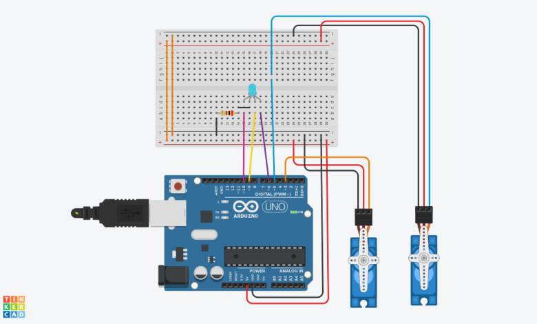
This project demonstrates how to control two micro servo motors based on simulated color signals from an RGB LED using an Arduino Uno. The RGB LED displays different colors to represent different control states, and the servos respond with specific mechanical movements according to the colour shown. This prototype is educational and intended to illustrate how colour-coded signals can trigger actuators in automation and robotics systems.
Component List:
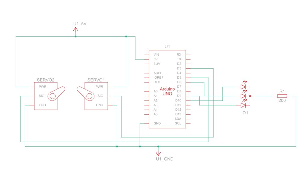
| Name | Quantity | Component |
|---|---|---|
| U1 | 1 | Arduino Uno R3 |
| SERVO1 SERVO2 | 2 | Positional Micro Servo |
| D1 | 1 | LED RGB |
| R1 | 1 | 200 Ω Resistor |
The Arduino Uno is programmed to cycle through several predefined RGB LED color combinations. Each color represents a unique control state. When a specific color is displayed on the LED, the two servos rotate to specified angles to perform a simulated action. The system repeats this cycle continuously, demonstrating the mapping between color signals and actuator response. Although this is a basic prototype without a colour sensor, it effectively models the logic used in real-world automation systems such as sorting machines and signal-controlled mechanisms. The circuit includes an RGB LED with a current-limiting resistor and two positional micro servos connected to the Arduino. This project is ideal for beginners learning about PWM, servo control, and conditional programming.
Arduino code:
#include <Servo.h>
Servo servo_5;
Servo servo_3;
void setup() {
pinMode(10, OUTPUT);
pinMode(9, OUTPUT);
pinMode(6, OUTPUT);
servo_5.attach(5, 500, 2500);
servo_3.attach(3, 500, 2500);
}
void loop() {
analogWrite(10, 255);
analogWrite(9, 0);
analogWrite(6, 0);
servo_5.write(0);
servo_3.write(0);
delay(2000);
servo_3.write(90);
servo_5.write(40);
delay(1000);
servo_3.write(0);
delay(1000);
analogWrite(10, 102);
analogWrite(9, 51);
analogWrite(6, 102);
servo_5.write(0);
servo_3.write(0);
delay(2000);
servo_3.write(45);
delay(2000);
servo_3.write(90);
servo_5.write(80);
delay(1000);
servo_3.write(0);
delay(1000);
analogWrite(10, 153);
analogWrite(9, 153);
analogWrite(6, 0);
servo_5.write(0);
servo_3.write(0);
delay(2000);
servo_3.write(45);
delay(2000);
servo_3.write(90);
servo_5.write(20);
delay(1000);
servo_3.write(0);
delay(1000);
servo_3.write(45);
delay(2000);
servo_3.write(90);
servo_5.write(10);
delay(1000);
servo_3.write(0);
delay(1000);
analogWrite(10, 0);
analogWrite(9, 0);
analogWrite(6, 153);
servo_5.write(0);
servo_3.write(0);
delay(2000);
servo_3.write(45);
delay(2000);
}
This project successfully demonstrates how color-coded signals can control servo motors using an Arduino Uno. By simulating different control states with an RGB LED, the system showcases the fundamental logic of automation and signal-based actuation. It provides a simple yet effective way to learn about PWM control, servo operation, and conditional programming, making it an excellent educational prototype for beginners in embedded systems and robotics.