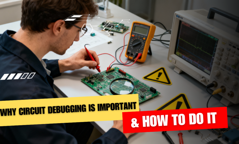
Circuit debugging is important because no circuit works perfectly the first time, and debugging is how you turn a non‑working idea into a reliable, repeatable design. It saves time, money, and frustration by letting you quickly find what is wrong instead of randomly changing parts and hoping it works.
Why circuit debugging matters
- Real circuits rarely behave exactly like simulations or diagrams, due to wiring mistakes, wrong values, noise, and faulty components.
- Debugging helps you isolate the real fault—whether it is power, wiring, components, or design—so you can fix the root cause instead of just “patching” symptoms.
- Learning to debug makes you a better designer: every bug you track down teaches you something about how circuits actually behave in the real world.
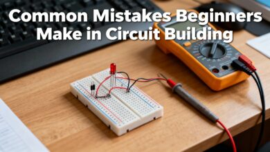
Step 1: Start with a calm visual check
Before powering anything, do a slow visual inspection of your breadboard or PCB.
Look for
- Loose wires, wrong connections, swapped pins, or parts in the wrong holes.
- Solder bridges, cracked joints, burnt or discoloured components, and bulging capacitors.
Often, a single misplaced jumper or reversed component is the entire problem.
Step 2: Verify power and ground first
If the circuit powers incorrectly, nothing else will behave. Use your multimeter to
- Check that the supply voltage at the board is what you expect (for example, exactly 5 V, not 7 V or 3.2 V).
- Confirm that ground is common across all modules, and there are no big unexpected voltage drops on power traces.
If the power rails are wrong, fix that before touching anything else.
Step 3: Compare “expected vs actual”
Use your schematic as a map. For key nodes, ask
- “What voltage or signal should be here?” (from theory, simulation, or datasheet).
- “What do I actually measure?” with a multimeter or oscilloscope.
Where expectation and reality first diverge, you are close to the fault.
Step 4: Divide and conquer the circuit
Do not treat a complex project as one giant black box. Break it into blocks
- Power section, sensor front‑end, microcontroller, output stage, communication, etc.
- Test each block on its own: for example, power up just the regulator, or feed a known signal into an amplifier and check its output.
By isolating blocks, you narrow the problem area quickly instead of chasing ghosts everywhere.
Step 5: Use the right tools smartly
Even a basic toolkit can take you far
- Multimeter: for DC voltages, continuity, resistance, and quick diode checks.
- Oscilloscope or USB scope: to see waveforms, glitches, resets, and communication signals that a meter cannot show.
- Logic analyzer: for digital buses like I²C, SPI, and UART, to see if timing and data are correct.
Always confirm your tools themselves work (for example, test the meter on a known battery) before trusting their readings.
Step 6: Test components and connections
If a specific block misbehaves
- Check resistors and diodes in‑circuit or out‑of‑circuit if readings look strange.
- Look for shorted or open capacitors and failed semiconductors; replace any part that looks physically damaged or reads wildly off from expected values.
Never assume a new part is automatically good—components can arrive faulty or be damaged by heat or wiring mistakes.
Step 7: Use simulation and documentation
For more complex designs, simulation tools (SPICE, Proteus, etc.) let you
- Verify if your idea works in theory before building.
- Compare simulated node voltages and waveforms with what you see on the bench to spot where hardware diverges.
Datasheets, app notes, and reference designs also show how the manufacturer expects a part to be wired and biased, which is very helpful when debugging.
Step 8: Work methodically and take notes
Good debugging is systematic, not random
- Change one thing at a time and record what happens.
- Mark tested nets and components on your printout or notes so you do not repeat work.
- When you finally fix the issue, note the root cause—future you will hit a similar bug someday.
Over time, you develop intuition: you start to “smell” power issues, grounding problems, or bad connectors just from symptoms, which is exactly what makes circuit debugging such an important skill for any electronics student or engineer.
This is all about Why Circuit Debugging Is Important & How to Do It, Thanks for reading.
Check out my other articles.