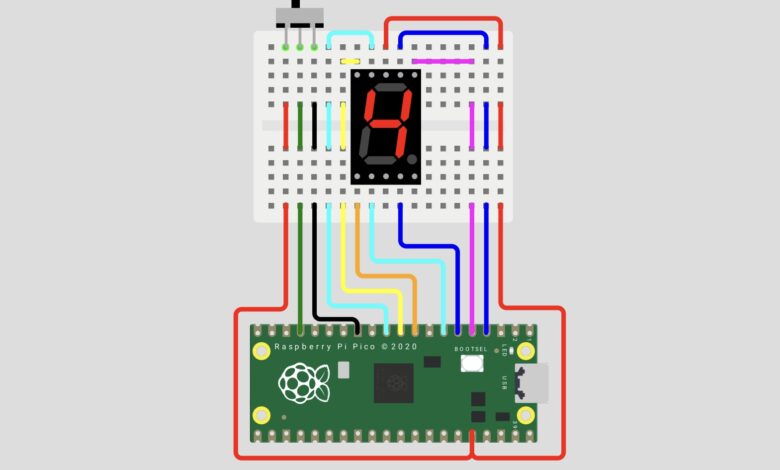
Want to learn how a 7-segment display works from scratch? In this project, we use a Raspberry Pi Pico and MicroPython to build a Hexadecimal Counter that counts from 0 to F (ascending) or F to 0 (descending) based on a slide switch input. This is a perfect project to understand how 7-segment displays work, how to control multiple GPIO pins, and how to write clean MicroPython code!
What You Will Learn :
- How a 7-segment display works and how to wire it
- How to control multiple GPIO pins with Raspberry Pi Pico
- How to write MicroPython code for the Pico
- How to use a slide switch as a direction input
Components Required :
| Component | Quantity |
|---|---|
| Raspberry Pi Pico | 1 |
| 7-Segment Display (Common Anode) | 1 |
| Slide Switch | 1 |
| Breadboard | 1 |
| Jumper Wires | Several |
| USB Cable (Micro USB) | 1 |
| Computer with Thonny IDE | 1 |
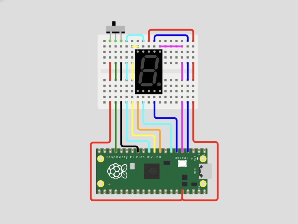
Circuit Diagram :
Wiring Table :
7-Segment Display → Raspberry Pi Pico
| Segment | Pico Pin | Wire Color |
|---|---|---|
| A | GP2 | Red |
| B | GP3 | Dark Green |
| C | GP4 | Black |
| D | GP5 | Yellow |
| E | GP6 | Cyan |
| F | GP7 | Orange |
| G | GP8 | Blue |
| Common Anode | 3.3V | Red |
Slide Switch → Raspberry Pi Pico
| Switch Pin | Pico Pin | Wire Color |
|---|---|---|
| Signal | GP13 | Cyan |
| VCC | 3.3V | Blue |
| GND | GND | Purple |
Note: This project uses a Common Anode 7-segment display. In a common anode display, segments turn ON with LOW (0) and turn OFF with HIGH (1).
How It Works :
- The Raspberry Pi Pico reads the state of the slide switch connected to GP13
- If the switch is HIGH (1), the counter counts ascending from 0 to F
- If the switch is LOW (0), the counter counts descending from F to 0
- Each digit is displayed for 1 second before moving to the next
- The counter automatically switches direction if the slide switch is toggled mid-count
Circuit Simulation :
Watch the 7-segment display count up and down in hexadecimal based on the slide switch position!
Arduino Code :
from machine import Pin
from utime import sleep


# 7-segment display layout
#       A
#      ---
#  F |  G  | B
#      ---
#  E |     | C
#      ---
#       D


pins = [
    Pin(2, Pin.OUT),  # A
    Pin(3, Pin.OUT),  # B
    Pin(4, Pin.OUT),  # C
    Pin(5, Pin.OUT),  # D
    Pin(6, Pin.OUT),  # E
    Pin(7, Pin.OUT),  # F
    Pin(8, Pin.OUT),  # G
    Pin(0, Pin.OUT)   # DP (not connected)
]

# Common anode 7-segment display digit patterns
digits = [
    [0, 0, 0, 0, 0, 0, 1, 1], # 0
    [1, 0, 0, 1, 1, 1, 1, 1], # 1
    [0, 0, 1, 0, 0, 1, 0, 1], # 2
    [0, 0, 0, 0, 1, 1, 0, 1], # 3
    [1, 0, 0, 1, 1, 0, 0, 1], # 4
    [0, 1, 0, 0, 1, 0, 0, 1], # 5
    [0, 1, 0, 0, 0, 0, 0, 1], # 6
    [0, 0, 0, 1, 1, 1, 1, 1], # 7
    [0, 0, 0, 0, 0, 0, 0, 1], # 8
    [0, 0, 0, 1, 1, 0, 0, 1], # 9
    [0, 0, 0, 1, 0, 0, 0, 1], # a
    [1, 1, 0, 0, 0, 0, 0, 1], # b
    [0, 1, 1, 0, 0, 0, 1, 1], # C
    [1, 0, 0, 0, 0, 1, 0, 1], # d
    [0, 1, 1, 0, 0, 0, 0, 1], # E
    [0, 1, 1, 1, 0, 0, 0, 1], # F
]

def reset():
    """Turns off all segments on the 7-segment display."""
    for pin in pins:
        pin.value(1)


reset()


switch = Pin(13, Pin.IN, Pin.PULL_DOWN)


while True:
    if switch.value() == 1:
        # Ascending counter
        for i in range(len(digits)):
            if switch.value() == 0:
                break
            for j in range(len(pins) - 1):
                pins[j].value(digits[i][j])
            sleep(1)
    else:
        # Descending counter
        for i in range(len(digits) - 1, -1, -1):
            if switch.value() == 1:
                break
            for j in range(len(pins) - 1):
                pins[j].value(digits[i][j])
            sleep(1)
Code Explanation :
Pin Setup: 8 pins are defined as outputs for the 7 segments (A to G) plus the decimal point (DP). Since this is a common anode display, segments are ON when the pin is LOW (0) and OFF when HIGH (1).
Digit Patterns: A 2D list stores the ON/OFF pattern for each of the 16 hexadecimal digits (0 to F). Each inner list has 8 values corresponding to segments A, B, C, D, E, F, G, and DP.
reset() Function: Sets all segment pins HIGH (1) to turn off the display completely. Called once at startup to ensure a clean start.
PULL_DOWN Switch: The switch uses the Pico’s internal pull-down resistor via Pin.PULL_DOWN, which prevents unstable floating pin readings without needing an external resistor.
Main Loop: Continuously checks the slide switch state. If HIGH, counts ascending from 0 to F. If LOW, counts descending from F to 0. The switch is checked mid-count so direction changes immediately without waiting for the full cycle to complete.
Speed: Each digit is displayed for 1 second giving viewers enough time to clearly read each digit including the hexadecimal letters a to F.
How to Use :
- Wire the circuit as shown in the diagram above
- Install Thonny IDE on your computer
- Connect Raspberry Pi Pico via USB while holding the BOOTSEL button
- Open Thonny and select MicroPython (Raspberry Pi Pico) as the interpreter
- Copy the code into Thonny and save it as main.py on the Pico
- Toggle the slide switch to change counting direction!
Customisation Tips :
- Change count speed: Modify sleep(1) to make the counter faster or slower
- Count only decimal: Remove the hex digits (a to F) from the digits list to count 0 to 9 only
- Add decimal point: Connect DP pin and set it LOW on certain digits to show a decimal point
- Add a push button: Use a push button instead of a slide switch to pause and resume the counter
- Expand to 2 digits: Add a second 7-segment display and use multiplexing to show 2-digit hex values (00 to FF)
Congratulations! You have successfully built a 7-Segment Hexadecimal Counter using Raspberry Pi Pico and MicroPython. This project is an excellent introduction to MicroPython programming, GPIO control, and 7-segment display interfacing. The hexadecimal counting feature makes it stand out from a typical 0 to 9 counter and gives you a deeper understanding of how computers represent numbers.
Try the customisation tips to take this project further and visit Tinkercircuits.com for more exciting Raspberry Pi Pico and Arduino projects!
Happy Tinkering! — The Tinker Circuits Team