What is a schematic?
A circuit diagram (schematic) is a visual map of an electrical design that shows how components connect electrically, not how they sit physically. It uses standardized symbols and labels so you can understand, build, and troubleshoot the circuit with confidence.
Schematic vs. wiring diagram
A schematic emphasizes function and signal flow using symbols and net labels. A wiring diagram shows physical locations, wire colours, and routing for real‑world assembly.
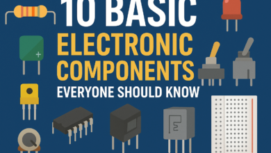
Meet the essential symbols
• Resistor (R): Limits current; values in Ω, kΩ, or MΩ.
• Capacitor (C): Stores charge; electrolytic types are polarized.
• Diode/LED (D): Conducts in one direction; LEDs have anode (+) and cathode (−).
• Transistor (Q): Electronic switch or amplifier (BJT or MOSFET).
• Integrated circuit (U): Multi‑pin device like a microcontroller or op‑amp.
• Power and ground: Supply nodes (e.g., 5V, 3.3V, VIN) and GND.
• Switch (S): Opens or closes a path.
• Connector (J): Interface to power, sensors, or external modules.
Reference designators and values
Each part has an ID (R1, C3, D2, U1) so you can track it across the page and the parts list. Values or part numbers near the symbol tell you what to buy and how the circuit is intended to behave.
- Find power and ground. Locate the main supply (VIN/5V/3.3V) and confirm a ground return.
- Follow the flow. Inputs are often on the left or top, outputs on the right or bottom.
- Trace the signal. Move block by block, noting how each component changes voltage or current.
- Check labels and pins. Match net names and pin numbers so you stay oriented.
- Confirm critical paths. Ensure every IC has power, ground, and any required reset or configuration pins.
- Park unknowns. When a symbol is unfamiliar, mark it and continue—come back after the first pass.
Nets, labels, and buses
Lines (wires) show direct connections. Net labels (e.g., SDA, TX, RESET, VCC) tie distant points together without drawing long lines. Buses group related signals (like data lines) to keep the drawing readable.
Power rails and decoupling
Power rails should be easy to spot and consistent across the sheet. Small capacitors near IC power pins stabilize the rail and tame noise—expect to see one or more per IC close to VCC and GND.
Polarity and orientation
Some parts must face the right way: electrolytic capacitors, diodes/LEDs, and many sensors or connectors. On the schematic, polarity is shown with plus/minus or symbol geometry; on parts, it appears as markings or notches.
The only formula you need
Ohm’s Law relates voltage, current, and resistance: V = I R. Use it to choose safe resistor values, estimate currents, and sanity‑check what a node should measure on a multimeter.
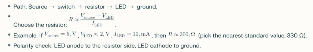
Mini walk‑through: LED with a resistor
Common building blocks
• Voltage divider: Two resistors creating a scaled voltage for sensing or biasing.
• RC filter: Resistor and capacitor used to smooth or filter signals and supplies.
• Pull‑up/pull‑down: Resistors that set a default logic level on inputs and reset lines.
From schematic to breadboard
Translate each symbol to a real part, then connect according to net names. Keep the schematic beside you and tick off each connection as you place jumpers to avoid missed grounds or swapped pins.
Troubleshooting with a schematic
• Verify power first: Measure rail voltages at the IC pins, not just at the connector.
• Walk the signal: Probe the output of each block to find where the expected level disappears.
• Compare intent vs. reality: If a node is stuck low, look for wrong resistor values, miswired nets, or reversed diodes/LEDs.
Clean reading habits
• Highlight in layers: Power nets first, grounds second, then signals.
• Sketch the blocks: Jot a mini map—Power → Control → Output—so you always know where you are.
• Note assumptions: If a value is missing, annotate your estimate and verify later.
Quick glossary
• Reference designator: The part’s ID on the schematic (R1, C5, U2).
• Net: An electrical connection shown by a line or shared label.
• Ground (GND): The common reference node for voltages and returns.
Practice tasks
• Add a pushbutton: Take the LED circuit and add a button with a pull‑down resistor; label every new net.
• Power audit: Pick any small schematic and highlight every decoupling capacitor and its nearest power pin.
• Re‑label for clarity: Rewrite long wires using net labels and group related signals into simple blocks.
FAQ
- How do I know a symbol’s orientation? Check for plus/minus, arrow direction, notches, or pin‑1 markers; if unsure, confirm with the component’s datasheet.
- Is a wiring diagram enough? Use wiring diagrams for physical assembly, but schematics are better for understanding and debugging.
- What multimeter checks help most? Rail voltage at IC pins, continuity of nets you’ve wired, and voltage at key nodes you’ve calculated with V = I R.
This is all about How to Read a Circuit Diagram, Thanks for reading.
Check out my other articles.