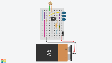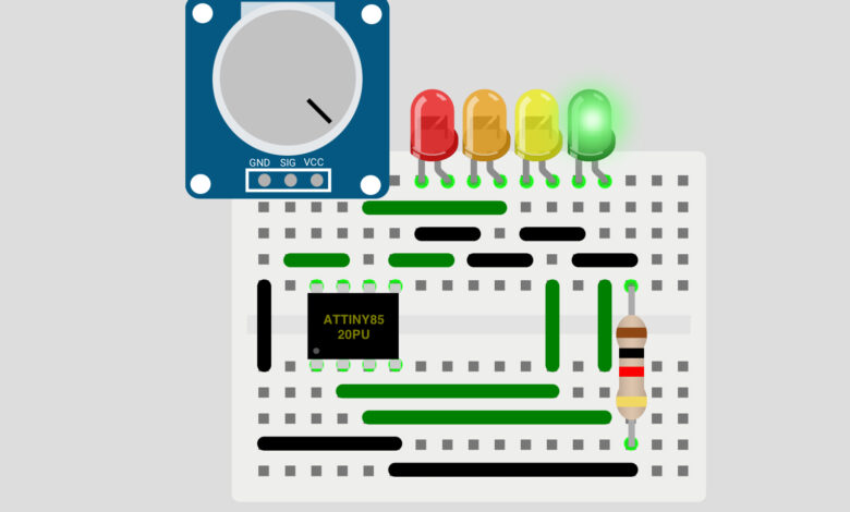
Ever wondered how much charge is left in your 3.7V LiPo battery? In this project, we build a smart Battery Level Indicator using an ATtiny85 microcontroller and 4 colored LEDs. Unlike traditional bar graph indicators, this project lights up only one LED at a time and changes color based on the battery level — Green for full, Yellow for good, Orange for low, and Red for critical. When the battery is dangerously low, the Red LED flashes as an urgent warning!
The best part? This entire project fits on a small breadboard using just the tiny ATtiny85 chip — no full Arduino board needed!
What You Will Learn :
- How to use the ATtiny85 microcontroller for a real world project
- How to read analog voltage using ATtiny85
- How to indicate battery levels using a single colour changing LED indicator
- How to implement a flashing warning LED in code
Components Required :
| Component | Quantity |
|---|---|
| ATtiny85 20PU Microcontroller | 1 |
| Red LED | 1 |
| Orange LED | 1 |
| Yellow LED | 1 |
| Green LED | 1 |
| Resistor (220Ω) | 1 |
| Potentiometer (to simulate battery voltage) | 1 |
| Breadboard | 1 |
| Jumper Wires | Several |
| USBasp Programmer (to upload code) | 1 |
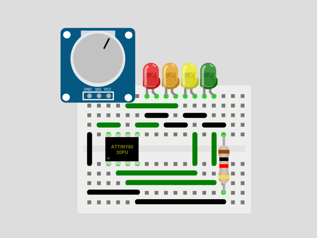
Circuit Diagram :
Wiring Table :
LEDs → ATtiny85
| LED Color | ATtiny85 Pin |
|---|---|
| Red | Pin 0 |
| Orange | Pin 1 |
| Yellow | Pin 3 |
| Green | Pin 4 |
Potentiometer → ATtiny85
| Potentiometer Pin | ATtiny85 Pin |
|---|---|
| GND | GND |
| SIG | A1 (Pin 2) |
| VCC | VCC |
Note: All LED cathodes are connected to GND through a shared 220Ω resistor. The potentiometer simulates the battery voltage input for testing. In a real build, connect the battery positive terminal directly to A1 through a voltage divider if needed.
How It Works :
Only one LED is ON at a time. As the battery drains, the active LED changes color giving a clear and intuitive visual indication of the battery status:
| Voltage | LED | Battery Status |
|---|---|---|
| Above 4.20V | Green ON | Full |
| 3.90V to 4.20V | Yellow ON | Good |
| 3.60V to 3.90V | Orange ON | Low |
| 3.30V to 3.60V | Red ON solid | Critical |
| 2.50V to 3.30V | Red FLASHING | Dead warning |
| Below 2.50V | All OFF | No battery |
When the voltage drops below 3.30V the Red LED starts flashing ON and OFF every 500ms as an urgent warning that the battery needs immediate charging.
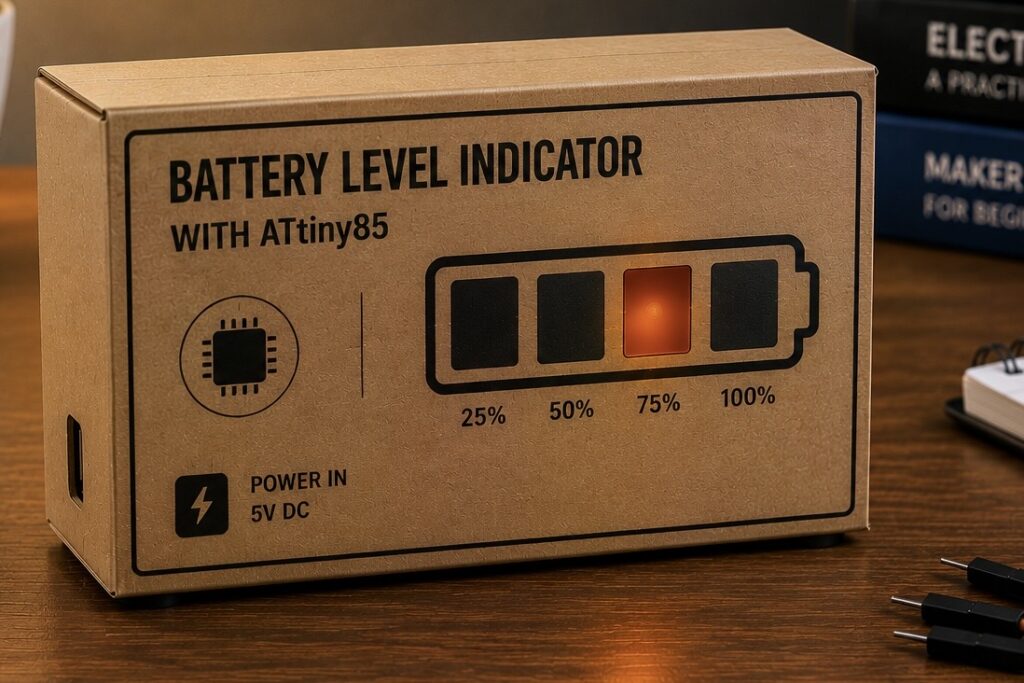
Circuit Simulation :
Watch the LED colour change as the potentiometer is turned to simulate different battery voltage levels!
Arduino Code :
#define RED_LED     0
#define ORANGE_LED  1
#define YELLOW_LED  3
#define GREEN_LED   4
#define BATTERY_PIN A1


// Voltage thresholds for a 3.7V LiPo battery
#define THRESH_GREEN  4.20
#define THRESH_YELLOW 3.90
#define THRESH_ORANGE 3.60
#define THRESH_RED    2.50
#define THRESH_FLASH  3.30


// Use 204.6 for 5V reference, 135.0 for 3.3V reference
#define VOLT_REF 204.6


float voltage;
bool flash;


void setup() {
  pinMode(BATTERY_PIN, INPUT);
  pinMode(RED_LED,    OUTPUT);
  pinMode(ORANGE_LED, OUTPUT);
  pinMode(YELLOW_LED, OUTPUT);
  pinMode(GREEN_LED,  OUTPUT);
}


void turnOffAll() {
  digitalWrite(RED_LED,    LOW);
  digitalWrite(ORANGE_LED, LOW);
  digitalWrite(YELLOW_LED, LOW);
  digitalWrite(GREEN_LED,  LOW);
}


void loop() {
  flash = !flash;
  voltage = analogRead(BATTERY_PIN) / VOLT_REF;


  turnOffAll();


  if (voltage >= THRESH_GREEN) {
    // Full battery - Green ON
    digitalWrite(GREEN_LED, HIGH);
  }
  else if (voltage >= THRESH_YELLOW) {
    // Good battery - Yellow ON
    digitalWrite(YELLOW_LED, HIGH);
  }
  else if (voltage >= THRESH_ORANGE) {
    // Low battery - Orange ON
    digitalWrite(ORANGE_LED, HIGH);
  }
  else if (voltage >= THRESH_RED) {
    // Critical battery - Red ON
    if (voltage < THRESH_FLASH) {
      // Flash red when dangerously low
      digitalWrite(RED_LED, flash);
    } else {
      digitalWrite(RED_LED, HIGH);
    }
  }
  // Below THRESH_RED - all LEDs off


  delay(500);
}
Code Explanation :
Pin and Threshold Definitions: All LED pins and voltage thresholds are defined at the top using #define. This makes it easy to adjust values without searching through the code.
VOLT_REF: Converts the raw analog reading (0-1023) to actual voltage. Use 204.6 for 5V reference or 135.0 for 3.3V reference depending on your ATtiny85 power supply.
turnOffAll() Function: Turns off all 4 LEDs at the start of every loop before deciding which single LED to turn on. This ensures only one LED is active at a time.
flash Variable: Toggles between true and false every loop cycle, used to create the flashing effect for the critical battery warning.
LED Logic: The if/else if chain checks the voltage from highest to lowest threshold and turns on only the matching LED. This ensures only one LED is on at a time giving a clean single colour indicator.
Flash Warning: When voltage drops below 3.30V, the red LED uses the flash variable to toggle ON and OFF every 500ms giving an urgent visual warning.
How to Upload Code to ATtiny85 :
Since ATtiny85 is not a standard Arduino board, you need a programmer to upload the code:
- Install ATtiny85 board support in Arduino IDE via File → Preferences → Additional Board URLs and add the ATtiny board manager URL
- Go to Tools → Board → ATtiny Microcontrollers → ATtiny85
- Set Clock to Internal 8MHz
- Connect your USBasp programmer to the ATtiny85
- Go to Tools → Programmer → USBasp
- Click Sketch → Upload Using Programmer
How to Use :
- Wire the circuit as shown in the diagram above
- Upload the code to the ATtiny85 using a USBasp programmer
- Connect a potentiometer to A1 to simulate battery voltage
- Turn the potentiometer and watch the single LED change color based on the voltage level
- For a real battery, connect the battery positive terminal to pin A1 (use a voltage divider if battery voltage exceeds 5V)
Customisation Tips :
- Change thresholds: Adjust the threshold values to match your specific battery chemistry or voltage range
- Change flash speed: Modify delay(500) to make the warning flash faster or slower
- Add a buzzer: Connect a small buzzer to a free pin and trigger it along with the red LED flash for an audible low battery warning
- Change voltage reference: Set VOLT_REF to 135.0 if your ATtiny85 runs on 3.3V instead of 5V
- Use with any battery: Adjust the thresholds to work with different battery types like 9V, 12V, or AA batteries using appropriate voltage dividers
- Add more levels: Connect more LEDs to free ATtiny85 pins for finer voltage resolution
You have successfully built a smart Battery Level Indicator using the tiny but powerful ATtiny85 microcontroller! The single color changing LED design is clean, intuitive, and compact — perfect for embedding into any battery-powered project. The flashing red warning gives you plenty of time to recharge before the battery dies completely.
Try embedding this into your next battery-powered project and never get caught with a dead battery again! Visit Tinkercircuits.com for more exciting projects!
Happy Tinkering! The Tinker Circuits Team