If you’re looking for a unique LED matrix project, this Arduino Mega MAX7219 Tunnel Animation is a great choice. The project creates a mesmerizing tunnel effect that appears to move endlessly through the LED display. Instead of using stored animation frames, the tunnel is generated mathematically in real time, resulting in smooth motion and efficient memory usage.
For this project, I used an Arduino Mega 2560 along with MAX7219 LED Matrix modules connected in a daisy-chain configuration. The Arduino calculates the tunnel pattern and continuously updates the display to create the animation effect.
Components Required :
| Component | Quantity |
| Arduino Mega 2560 | 1 |
| MAX7219 8*8 LED Matrix Module | 16 |
| Jumper Wires | As Required |
| USB Cable | 1 |
Circuit Connections :
The MAX7219 modules communicate with the Arduino Mega using SPI communication.
| Arduino Mega | MAX7219 |
| 5V | VCC |
| GND | GND |
| D11 | DIN |
| D10 | CS |
| D13 | CLK |
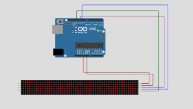
Circuit Diagram :
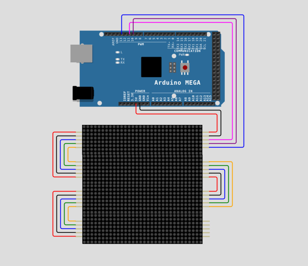
Connect the first matrix module directly to the Arduino Mega using the connections above. The remaining matrix modules are connected in a daisy-chain arrangement where the output of one module is connected to the input of the next module.
After completing the wiring, connect the Arduino Mega to your computer using a USB cable.
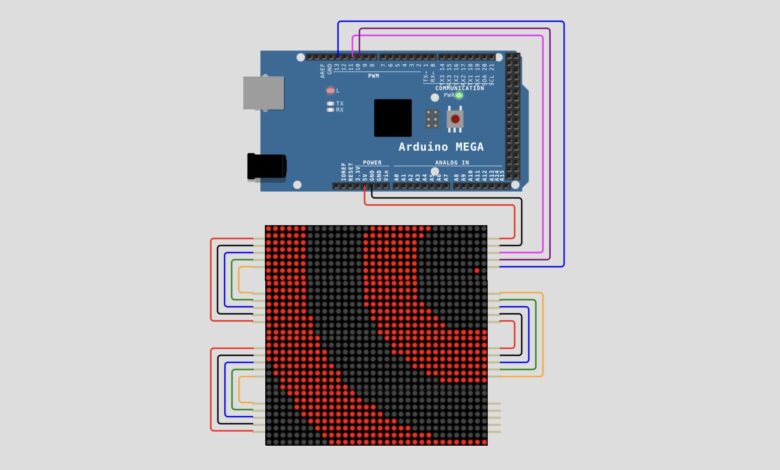
Circuit Simulation :
Arduino Code :
Once the wiring is complete, open the Arduino IDE and create a new sketch. Copy the complete tunnel animation code and upload it to the Arduino Mega.
#define CLK 13
#define DIN 11
#define CS 10
#define X_SEGMENTS 4
#define Y_SEGMENTS 4
#define NUM_SEGMENTS (X_SEGMENTS * Y_SEGMENTS)


byte fb[8 * NUM_SEGMENTS];


void shiftAll(byte send_to_address, byte send_this_data) {
  digitalWrite(CS, LOW);
  for (int i = 0; i < NUM_SEGMENTS; i++) {
    shiftOut(DIN, CLK, MSBFIRST, send_to_address);
    shiftOut(DIN, CLK, MSBFIRST, send_this_data);
  }
  digitalWrite(CS, HIGH);
}


void setup() {
  Serial.begin(115200);
  pinMode(CLK, OUTPUT);
  pinMode(DIN, OUTPUT);
  pinMode(CS, OUTPUT);


  shiftAll(0x0f, 0x00);
  shiftAll(0x0b, 0x07);
  shiftAll(0x0c, 0x01);
  shiftAll(0x0a, 0x0f);
  shiftAll(0x09, 0x00);
}


void loop() {
  static int16_t sx1 = 15 << 8, sx2 = sx1, sy1, sy2;


  sx1 = sx1 - (sy1 >> 6);
  sy1 = sy1 + (sx1 >> 6);
  sx2 = sx2 - (sy2 >> 5);
  sy2 = sy2 + (sx2 >> 5);


  static byte travel = 0;
  travel--;


  byte *dst = fb;
  byte output = 0;


  int8_t x_offset = (sx1 >> 8) - X_SEGMENTS * 4;
  int8_t y_offset = (sx2 >> 8) - Y_SEGMENTS * 4;


  uint8_t screenx, screeny, xroot, yroot;
  uint16_t xsumsquares, ysumsquares, xnextsquare, ynextsquare;
  int8_t x, y;


  x = x_offset;
  y = y_offset;


  ysumsquares = x_offset * x_offset + y * y;
  yroot = int(sqrt(ysumsquares));
  ynextsquare = yroot * yroot;


  screeny = Y_SEGMENTS * 8;


  while (y < 0 && screeny) {
    x = x_offset;
    screenx = X_SEGMENTS * 8;
    xsumsquares = ysumsquares;
    xroot = yroot;


    if (x < 0) {
      xnextsquare = xroot * xroot;


      while (x < 0 && screenx) {
        screenx--;
        output <<= 1;
        output |= ((xroot + travel) & 8) >> 3;


        if (!(screenx & 7))
          *dst++ = output;


        xsumsquares += 2 * x++ + 1;


        if (xsumsquares < xnextsquare)
          xnextsquare -= 2 * xroot-- - 1;
      }
    }


    if (screenx) {
      xnextsquare = (xroot + 1) * (xroot + 1);


      while (screenx) {
        screenx--;
        output <<= 1;
        output |= ((xroot + travel) & 8) >> 3;


        if (!(screenx & 7))
          *dst++ = output;


        xsumsquares += 2 * x++ + 1;


        if (xsumsquares >= xnextsquare)
          xnextsquare += 2 * ++xroot + 1;
      }
    }


    ysumsquares += 2 * y++ + 1;


    if (ysumsquares < ynextsquare)
      ynextsquare -= 2 * yroot-- - 1;


    screeny--;
  }


  ynextsquare = (yroot + 1) * (yroot + 1);


  while (screeny) {
    x = x_offset;
    screenx = X_SEGMENTS * 8;
    xsumsquares = ysumsquares;
    xroot = yroot;


    if (x < 0) {
      xnextsquare = xroot * xroot;


      while (x < 0 && screenx) {
        screenx--;
        output <<= 1;
        output |= ((xroot + travel) & 8) >> 3;


        if (!(screenx & 7))
          *dst++ = output;


        xsumsquares += 2 * x++ + 1;


        if (xsumsquares < xnextsquare)
          xnextsquare -= 2 * xroot-- - 1;
      }
    }


    if (screenx) {
      xnextsquare = (xroot + 1) * (xroot + 1);


      while (screenx--) {
        output <<= 1;
        output |= ((xroot + travel) & 8) >> 3;


        if (!(screenx & 7))
          *dst++ = output;


        xsumsquares += 2 * x++ + 1;


        if (xsumsquares >= xnextsquare)
          xnextsquare += 2 * ++xroot + 1;
      }
    }


    ysumsquares += 2 * y++ + 1;


    if (ysumsquares >= ynextsquare)
      ynextsquare += 2 * ++yroot + 1;


    screeny--;
  }


  show();
}


void set_pixel(uint8_t x, uint8_t y, uint8_t mode) {
  byte *addr = &fb[x / 8 + y * X_SEGMENTS];
  byte mask = 128 >> (x % 8);


  switch (mode) {
    case 0:
      *addr &= ~mask;
      break;
    case 1:
      *addr |= mask;
      break;
    case 2:
      *addr ^= mask;
      break;
  }
}


void safe_pixel(uint8_t x, uint8_t y, uint8_t mode) {
  if ((x >= X_SEGMENTS * 8) || (y >= Y_SEGMENTS * 8))
    return;


  set_pixel(x, y, mode);
}


void clear() {
  byte *addr = fb;


  for (byte i = 0; i < 8 * NUM_SEGMENTS; i++)
    *addr++ = 0;
}


void show() {
  for (byte row = 0; row < 8; row++) {
    digitalWrite(CS, LOW);


    byte segment = NUM_SEGMENTS;


    while (segment--) {
      byte x = segment % X_SEGMENTS;
      byte y = segment / X_SEGMENTS * 8;
      byte addr = (row + y) * X_SEGMENTS;


      if (segment & X_SEGMENTS) {
        shiftOut(DIN, CLK, MSBFIRST, 8 - row);
        shiftOut(DIN, CLK, LSBFIRST, fb[addr + x]);
      } else {
        shiftOut(DIN, CLK, MSBFIRST, 1 + row);
        shiftOut(DIN, CLK, MSBFIRST, fb[addr - x + X_SEGMENTS - 1]);
      }
    }


    digitalWrite(CS, HIGH);
  }
}
After uploading the code, the Arduino initializes all MAX7219 modules and creates a framebuffer to store the display data. Instead of loading images from memory, the sketch calculates the distance of every LED from a moving center point.
These calculations generate circular rings that continuously move across the display. As the rings shift, the animation creates the illusion of traveling through a tunnel.
The movement is controlled by a variable called travel, while the frame buffer ensures that the animation remains smooth and flicker-free.
Once the code is uploaded successfully, the LED matrix display starts generating animated circular patterns. The rings move continuously, producing an impressive tunnel effect across the entire display.
This project demonstrates how mathematical calculations can be used to create real-time graphics on LED matrices using an Arduino Mega and MAX7219 display modules.
Happy Tinkering! — The Tinker Circuits Team