Looking for a fun and simple project to get started with the XIAO ESP32-C3? In this project, we will blink three colored LEDs — Red, Green, and Blue — one after the other using the Seeed Studio XIAO ESP32-C3 microcontroller. This is a perfect beginner project that teaches you the basics of digital output pins and LED control!
What You Will Learn :
- How to set up and use the XIAO ESP32-C3
- How to control digital output pins
- How to blink multiple LEDs in sequence
Components Required :
| Component | Quantity |
|---|---|
| Seeed Studio XIAO ESP32-C3 | 1 |
| Red LED | 1 |
| Green LED | 1 |
| Blue LED | 1 |
| Resistors (220Ω) | 3 |
| Jumper Wires | Several |
| USB Cable | 1 |
| Computer with Arduino IDE | 1 |
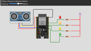
Circuit Diagram :
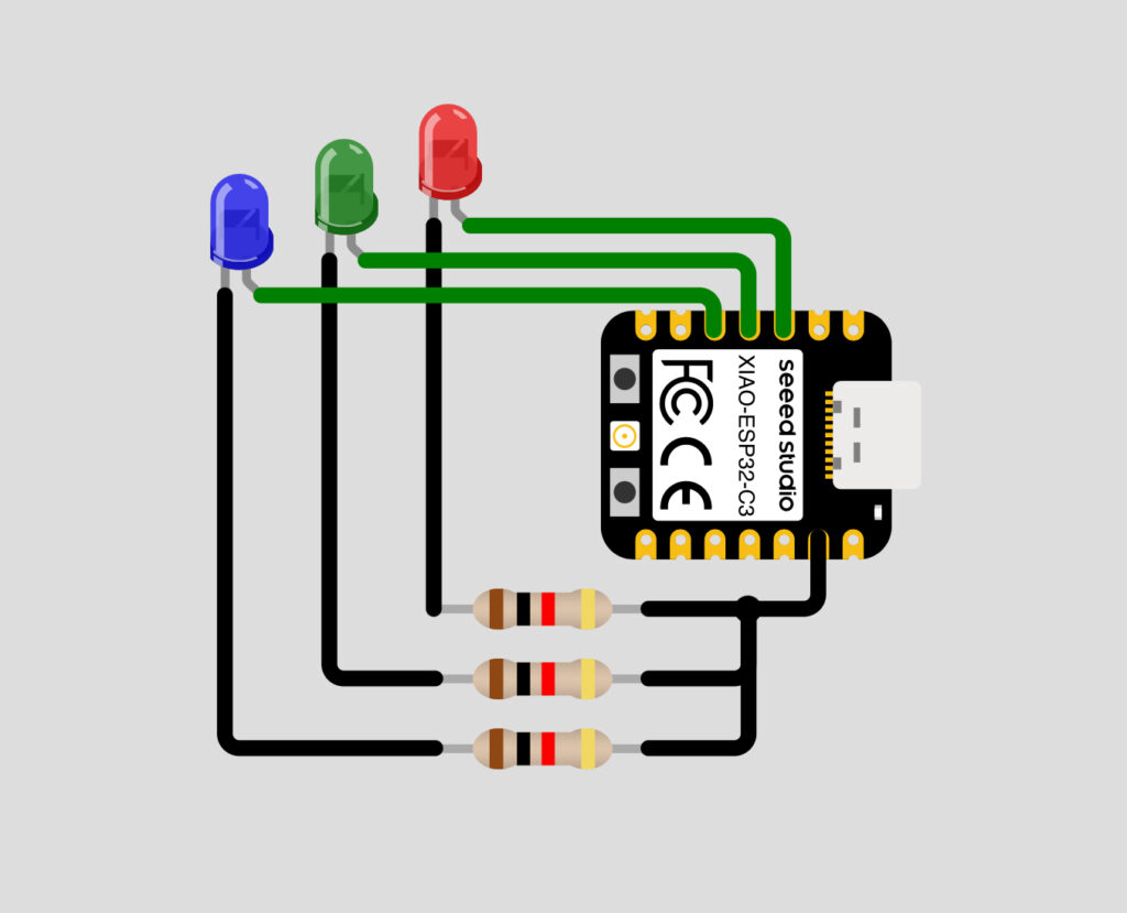
Wiring Table :
| LED | XIAO ESP32-C3 Pin | Resistor |
|---|---|---|
| Red | D2 | 220Ω |
| Green | D3 | 220Ω |
| Blue | D4 | 220Ω |
Note: Connect the longer leg (anode) of each LED to the signal pin through a resistor, and the shorter leg (cathode) to GND.
How It Works :
The XIAO ESP32-C3 controls three LEDs connected to pins D2, D3, and D4. In the loop, each LED is turned ON for 500 milliseconds and then turned OFF before the next LED turns ON. This creates a smooth sequential blinking effect cycling through Red, Green, and Blue continuously.
Circuit Simulation :
Watch the Red, Green, and Blue LEDs blink one after the other in action!
Arduino Code :
void setup() {
Serial.begin(115200);
pinMode(D2, OUTPUT);
pinMode(D3, OUTPUT);
pinMode(D4, OUTPUT);
Serial.println("");
Serial.println("Hello, XIAO ESP32-C3!");
Serial.println("Welcome to Tinkercircuits!");
}
void loop() {
Serial.println("Red");
digitalWrite(D2, HIGH);
delay(500);
digitalWrite(D2, LOW);
Serial.println("Green");
digitalWrite(D3, HIGH);
delay(500);
digitalWrite(D3, LOW);
Serial.println("Blue");
digitalWrite(D4, HIGH);
delay(500);
digitalWrite(D4, LOW);
}
Code Explanation :
Setup: Initialises Serial communication at 115200 baud and sets pins D2, D3, and D4 as OUTPUT for the three LEDs.
Loop: Each LED is turned ON using digitalWrite(pin, HIGH), held for 500ms using delay(500), then turned OFF using digitalWrite(pin, LOW). This repeats continuously for Red, Green, and Blue in sequence.
How to Use :
- Wire the circuit as shown in the diagram above
- Install Arduino IDE and add XIAO ESP32-C3 board support
- Copy and upload the code to your XIAO ESP32-C3
- Watch the Red, Green, and Blue LEDs blink one by one!
Customisation Tips :
- Change blink speed: Modify the delay(500) value, lower = faster blink
- Change blink order: Rearrange the Red, Green, Blue blocks in the loop
- Blink all together: Use digitalWrite on all three pins at the same time
- Add more LEDs: Connect additional LEDs to other free pins and add them to the sequence
- Add a button: Use a button to start/stop the blinking sequence
Congratulations! You have successfully built an RGB LED Blink project using the XIAO ESP32-C3. This simple project is a great starting point for learning how to control output pins and LEDs. From here, you can expand to more complex lighting effects, button controls, or even WiFi-controlled LEDs using the ESP32-C3s built-in WiFi!
Keep experimenting and visit Tinkercircuits.com for more exciting projects!
Happy Tinkering! — The Tinker Circuits Team