The Interactive Quiz Game with Arduino brings education and entertainment together in an engaging project. Using a LiquidCrystal display and buttons, this project challenges users with quiz questions, allowing them to select answers and receive immediate feedback.
The LCD screen provides a user-friendly interface, displaying questions and multiple-choice options. The game utilises buttons for user input, making it interactive and accessible.
Circuit Diagram :
Component List:
| Name | Quantity | Component |
|---|---|---|
| U1 | 1 | Arduino Uno R3 |
| U2 | 1 | LCD 16 x 2 |
| Rpot1 | 1 | 250 kΩ Potentiometer |
| S1 S2 S3 S4 | 4 | Pushbutton |
| R1 | 1 | 1 kΩ Resistor |
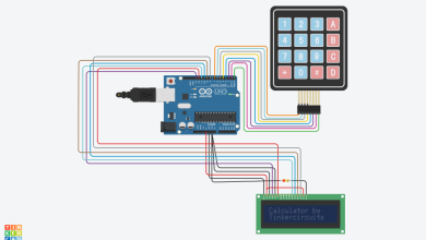
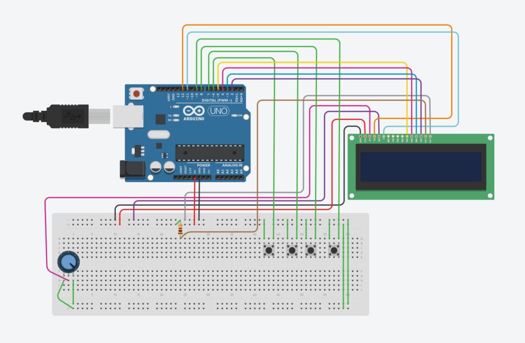
The circuit employs a LiquidCrystal display connected to pins 12, 11, 5, 4, 3, and 2 on the Arduino. Additionally, four buttons are connected to pins 6, 7, 8, and 9.
The buttons serve as input devices for users to select their answers during the quiz. The use of INPUT_PULLUP ensures a straightforward setup without the need for external resistors.
Circuit Simulation :
Arduino Code:
#include <LiquidCrystal.h>


LiquidCrystal lcd(12, 11, 5, 4, 3, 2);


const int buttonPins[] = {6, 7, 8, 9};
const int numButtons = sizeof(buttonPins) / sizeof(buttonPins[0]);


const int QUESTION_TIME = 4000;
const int OPTION_TIME = 3000;
const int RESULT_TIME = 2000;


const int numQuestions = 10;


const char* questions[numQuestions] = {
  "What is 2 + 2?",
  "Unit of current?",
  "Ohm's law: V=?",
  "Arduino Uno MCU?",
  "LED is a?",
  "Uno logic level?",
  "Capacitor unit?",
  "ESP32 has WiFi?",
  "Binary 101 = ?",
  "I2C signal wires"
};


const char* options[numQuestions][4] = {
  {"3", "4", "5", "6"},
  {"Volt", "Amp", "Ohm", "Watt"},
  {"I*R", "I/R", "R/I", "I+R"},
  {"ESP8266", "ATmega328P", "ATtiny85", "STM32"},
  {"Diode", "Resistor", "Switch", "Battery"},
  {"1.8V", "3.3V", "5V", "12V"},
  {"Henry", "Tesla", "Joule", "Farad"},
  {"Yes", "No", "Only BT", "Only USB"},
  {"3", "4", "5", "6"},
  {"1", "2", "3", "4"}
};


const int correctAnswers[numQuestions] = {2, 2, 1, 2, 1, 3, 4, 1, 3, 2};


void setup() {
  lcd.begin(16, 2);
  lcd.print("Welcome to the");
  lcd.setCursor(0, 1);
  lcd.print("Quiz Game!");
  delay(2000);
  lcd.clear();


  for (int i = 0; i < numButtons; ++i) {
    pinMode(buttonPins[i], INPUT_PULLUP);
  }
}


void loop() {
  for (int q = 0; q < numQuestions; ++q) {
    lcd.clear();
    lcd.print("Question ");
    lcd.print(q + 1);
    lcd.print(":");
    lcd.setCursor(0, 1);
    lcd.print(questions[q]);
    delay(QUESTION_TIME);
    lcd.clear();


    for (int i = 0; i < 4; ++i) {
      lcd.setCursor(0, 1);
      lcd.print(i + 1);
      lcd.print(") ");
      lcd.print(options[q][i]);
      delay(OPTION_TIME);
      lcd.clear();
    }


    int selectedAnswer = waitForButtonPress();


    lcd.clear();
    lcd.print("You chose: ");
    lcd.print(selectedAnswer);
    lcd.setCursor(0, 1);
    if (selectedAnswer == correctAnswers[q]) {
      lcd.print("Correct!");
    } else {
      lcd.print("Incorrect.");
    }
    delay(RESULT_TIME);
  }
}


int waitForButtonPress() {
  while (true) {
    for (int i = 0; i < numButtons; ++i) {
      if (digitalRead(buttonPins[i]) == LOW) {
        return i + 1;
      }
    }
  }
}
This Arduino-based quiz game offers a fun and educational experience. Users are welcomed with a greeting, presented with questions, and provided with multiple-choice options. The immediate feedback on their chosen answers enhances the learning experience.
The project is an excellent example of combining hardware components and programming logic to create an interactive and entertaining application.
As a starting point for Arduino enthusiasts, it showcases the potential for incorporating technology into educational games.
Visit Tinkercircuits.com for more exciting blogs!
Happy Tinkering! The Tinker Circuits Team