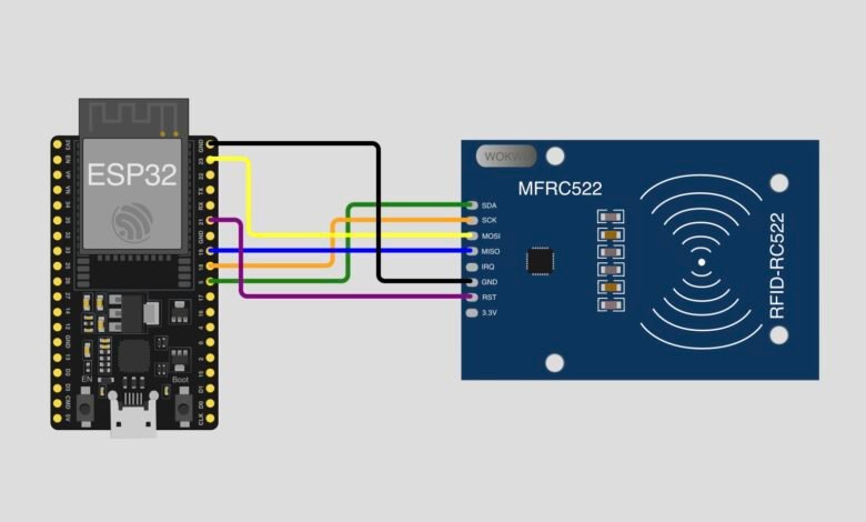
RFID is everywhere, from door access cards and bus passes to inventory tags and smart lockers. In this project, we build an RFID card reader using an ESP32 and the popular MFRC522 module. Hold a card or tag near the reader, and the ESP32 reads its unique ID (UID) and prints it on the Serial Monitor.
Every RFID card has its own UID, so reading it is the first step for projects like door locks, attendance systems and access control. Once you can read a card, you can make your ESP32 react to it in any way you like!
What You Will Learn :
- How to connect an MFRC522 RFID module to an ESP32
- How the SPI pins of the ESP32 are used to talk to the reader
- How to detect a new RFID card or tag
- How to read the UID of a card and print it in hexadecimal
- How to show the output on the Serial Monitor
Components Required :
| Component | Quantity |
| ESP32 DevKit Board | 1 |
| MFRC522 RFID Module (with card and key tag) | 1 |
| Jumper Wires | 7 |
| Micro USB Cable (to upload code) | 1 |
Libraries Required :
| Library | Purpose |
| MFRC522 | Driver for the MFRC522 RFID reader |
| SPI | SPI communication (built into the ESP32 board package) |
Install the MFRC522 library from Sketch → Include Library → Manage Libraries in the Arduino IDE. If you have not added ESP32 support yet, open Tools → Board → Boards Manager, search for esp32 and install the package.
Circuit Diagram :
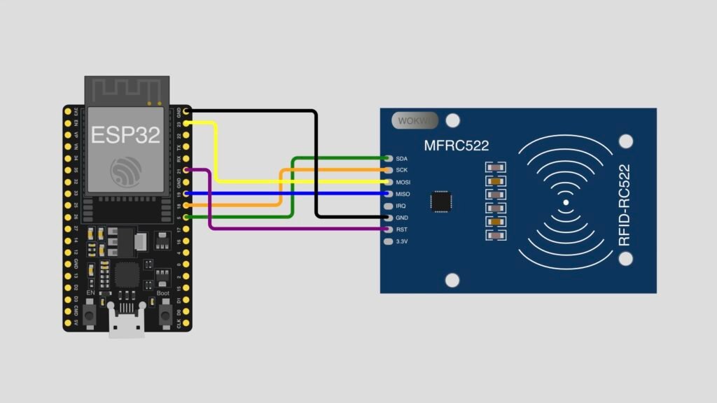
Wiring Table :
MFRC522 RFID Module → ESP32
| MFRC522 Pin | ESP32 Pin |
| SDA (SS) | GPIO 5 |
| SCK | GPIO 18 |
| MOSI | GPIO 23 |
| MISO | GPIO 19 |
| RST | GPIO 21 |
| 3.3V (VCC) | 3V3 |
| GND | GND |
Note: The MFRC522 module works at 3.3V only. Never connect it to the 5V pin, because it can damage the module. The IRQ pin is not used in this project, so leave it unconnected. GPIO 18, 19 and 23 are the default SPI pins of the ESP32.
How It Works :
The MFRC522 module creates a small radio field. When an RFID card or tag enters this field, the card powers up and sends its UID back to the reader. The reader passes the UID to the ESP32 over the SPI connection, and the ESP32 prints it on the Serial Monitor.
In the code, the ESP32 keeps checking whether a new card is present. When it finds one, it reads the card, prints each byte of the UID in hexadecimal, and then waits one second before looking for the next card.
| Step | What Happens | Serial Monitor Output |
| 1 | The ESP32 starts up | MFRC522 Ready |
| 2 | A card is brought near the reader | UID::DE:AD:BE:EF |
| 3 | The card is halted and the ESP32 waits 1 second | Ready for the next card |
The UID DE:AD:BE:EF is the example card used in the simulation. A real card will show a different UID.
Circuit Simulation :
Watch the ESP32 read the RFID card and print its UID on the Serial Monitor!
Arduino Code :
#include <SPI.h>
#include <MFRC522.h>


#define SS_PIN 5
#define RST_PIN 21


MFRC522 rfid(SS_PIN, RST_PIN);


void setup() {
  Serial.begin(115200);
  SPI.begin();
  rfid.PCD_Init();
  Serial.println("MFRC522 Ready");
}


void loop() {
  delay(10);


  if (!rfid.PICC_IsNewCardPresent()) {
    return;
  }


  if (!rfid.PICC_ReadCardSerial()) {
    return;
  }


  Serial.print("UID:");
  for (byte i = 0; i < rfid.uid.size; i++) {
    Serial.print(rfid.uid.uidByte[i] < 0x10 ? ":0" : ":");
    Serial.print(rfid.uid.uidByte[i], HEX);
  }
  Serial.println();


  rfid.PICC_HaltA();
  delay(1000);
}
Code Explanation :
Library Includes: SPI.h handles the SPI communication, and MFRC522.h gives us the functions to control the RFID reader.
Pin Definitions: SS_PIN is set to 5 and RST_PIN is set to 21. These match the wires connected to the SDA and RST pins of the module.
Creating the Reader: MFRC522 rfid(SS_PIN, RST_PIN) creates the reader object using those two pins.
Setup: Serial.begin(115200) starts the Serial Monitor. SPI.begin() starts the SPI bus on the default ESP32 pins, and rfid.PCD_Init() starts the reader. Then the message “MFRC522 Ready” is printed.
Looking for a Card: PICC_IsNewCardPresent() checks if a new card is in range. If there is none, the loop() returns and checks again. The small delay(10) keeps the loop from running too fast.
Reading the Card: PICC_ReadCardSerial() reads the UID from the card. If the read fails, the loop returns and tries again.
Printing the UID: The for loop goes through every byte of the UID. Each byte is printed in hexadecimal, and a 0 is added in front of any byte below 0x10, so every byte shows two digits.
Halting the Card: PICC_HaltA() tells the card to stop communicating, so the same card is not read again and again. The one second delay gives you time to remove the card before the next scan.
How to Use :
- Wire the circuit as shown in the diagram above
- Install the MFRC522 library in the Arduino IDE
- Connect the ESP32 to your computer with a micro USB cable
- Select Tools → Board and choose your ESP32 board, for example ESP32 Dev Module
- Select the correct port under Tools → Port
- Upload the code to the ESP32
- Open the Serial Monitor and set the speed to 115200 baud
- Wait for the “MFRC522 Ready” message
- Bring an RFID card or key tag close to the reader
- Read the UID printed on the Serial Monitor
Customisation Tips :
- Build an access control system: Compare the UID of each card with a saved list, and allow or deny access
- Add an LED indicator: Turn on a green LED for an accepted card and a red LED for an unknown card
- Add a buzzer: Play a short beep every time a card is read
- Control a lock: Connect a relay module or a servo motor to open a door or a box when the right card is scanned
- Show the result on a display: Add an OLED or LCD to show the UID or a welcome message
- Make an attendance system: Connect the ESP32 to WiFi and send each UID to an online sheet or database
- Clean up the output: Change the print lines in the loop to remove the extra colon at the start of the UID
You have successfully built an RFID card reader using an ESP32 and the MFRC522 module. With just seven wires and a short sketch, you can now read the unique ID of any compatible card or tag. This is the foundation for door locks, attendance systems, smart lockers and many other projects.
Try saving the UID of your own card and making the ESP32 react only to it! Visit Tinkercircuits.com for more exciting projects!
Happy Tinkering! The Tinker Circuits Team