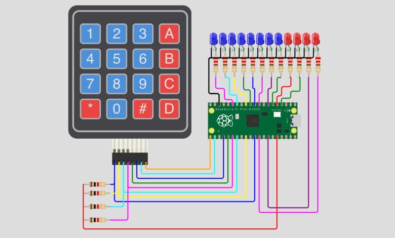
Have you ever wanted to control a row of LEDs with just the press of a key? In this project, we build a keypad-controlled LED panel using a Raspberry Pi Pico, a 4×4 matrix keypad and 12 LEDs. Each key on the keypad is linked to an LED, so pressing a key turns the matching light on.
The panel has 8 blue LEDs for the number keys and 4 red LEDs for the letter keys. There are also group keys, so you can switch a whole set of LEDs on or off with one press. It is a great way to learn how a matrix keypad works and how to control many outputs from a single board.
What You Will Learn :
- How to connect a 4×4 matrix keypad to a Raspberry Pi Pico
- How to read key presses using the Keypad library
- How to control 12 LEDs from different Pico pins
- How to use arrays to keep pin numbers organized
- How to use a switch statement to run a different action for each key
Components Required :
| Component | Quantity |
| Raspberry Pi Pico | 1 |
| 4×4 Matrix Membrane Keypad | 1 |
| Blue LEDs | 8 |
| Red LEDs | 4 |
| 220 Ohm Resistors | 12 |
| 1k Ohm Resistors (optional) | 4 |
| Breadboard | 1 |
| Jumper Wires | Several |
| Micro USB Cable (to upload code) | 1 |
Libraries Required :
| Library | Purpose |
| Keypad | Reads the 4×4 matrix keypad |
Install the Keypad library (by Mark Stanley and Alexander Brevig) from Sketch → Include Library → Manage Libraries in the Arduino IDE. If you have not added Raspberry Pi Pico support yet, open Tools → Board → Boards Manager, search for Raspberry Pi Pico and install the package.
Circuit Diagram :
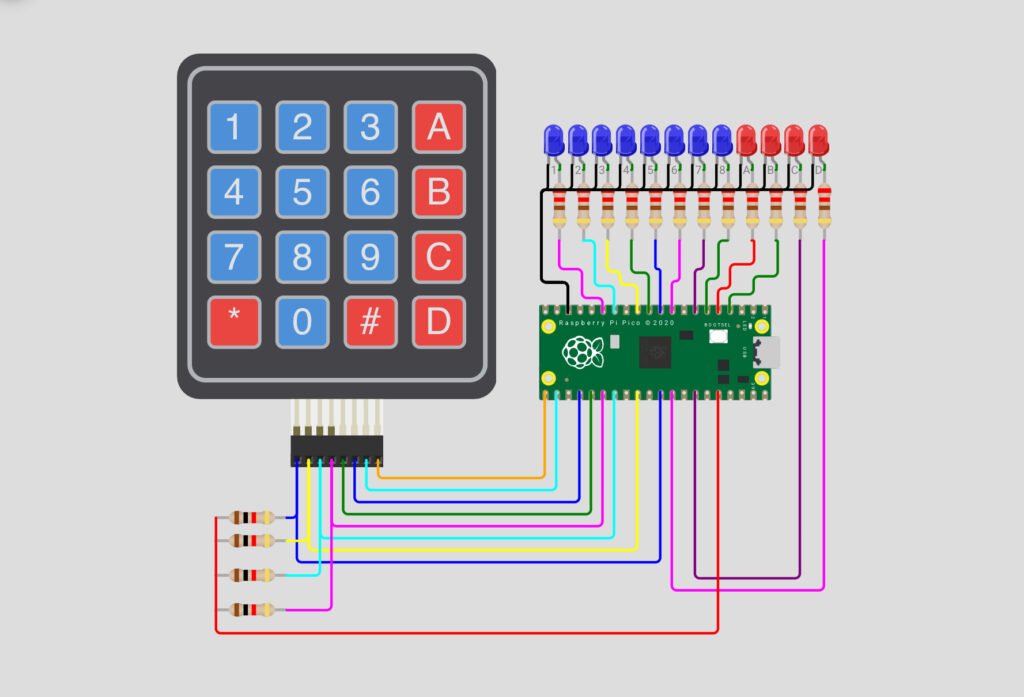
Wiring Table :
Keypad → Raspberry Pi Pico
| Keypad Pin | Pico Pin |
| R1 | GP26 |
| R2 | GP22 |
| R3 | GP21 |
| R4 | GP20 |
| C1 | GP19 |
| C2 | GP18 |
| C3 | GP17 |
| C4 | GP16 |
LEDs → Raspberry Pi Pico (each LED has a 220 ohm resistor in series)
| LED | Color | Pico Pin |
| 1 | Blue | GP11 |
| 2 | Blue | GP10 |
| 3 | Blue | GP9 |
| 4 | Blue | GP8 |
| 5 | Blue | GP7 |
| 6 | Blue | GP6 |
| 7 | Blue | GP5 |
| 8 | Blue | GP4 |
| A | Red | GP3 |
| B | Red | GP2 |
| C | Red | GP28 |
| D | Red | GP27 |
Note: Connect the resistor between each Pico pin and the longer leg (anode) of its LED. Join the shorter legs (cathodes) of all 12 LEDs together and connect them to a GND pin on the Pico. The four 1k ohm resistors in the circuit connect each keypad row line to the 3V3 pin as pull-ups. The Keypad library already turns on internal pull-ups on the row pins, so these resistors are optional.
How It Works :
A 4×4 keypad has 16 keys but only 8 wires. The keys are arranged in a grid of 4 rows and 4 columns, and pressing a key connects one row to one column. The Keypad library scans the grid again and again and tells the Pico which key was pressed.
When the Pico gets a key, it lights up the LED linked to that key. All LEDs are off when the board starts.
| Key | What Happens |
| 1 to 8 | Turns on the matching blue LED |
| 9 | Turns on all 8 blue LEDs |
| 0 | Turns off all 8 blue LEDs |
| A, B, C, D | Turns on the matching red LED |
| * | Turns on all 4 red LEDs |
| # | Turns off all 4 red LEDs |
The keys for single LEDs only turn them on. To switch LEDs off, use the group keys: 0 for the blue LEDs and # for the red LEDs.
Circuit Simulation :
Watch the LEDs light up as each key on the keypad is pressed!
Arduino Code :
#include <Keypad.h>


const uint8_t LEDS = 12;
const uint8_t ROWS = 4;
const uint8_t COLS = 4;


char keys[ROWS][COLS] = {
  { '1', '2', '3', 'A' },
  { '4', '5', '6', 'B' },
  { '7', '8', '9', 'C' },
  { '*', '0', '#', 'D' }
};


uint8_t ledPins[LEDS] = { 11, 10, 9, 8, 7, 6, 5, 4, 3, 2, 28, 27 };
uint8_t rowPins[ROWS] = { 26, 22, 21, 20 };
uint8_t colPins[COLS] = { 19, 18, 17, 16 };


Keypad keypad = Keypad(makeKeymap(keys), rowPins, colPins, ROWS, COLS);


void setup() {
  for (uint8_t l = 0; l < LEDS; l++) {
    pinMode(ledPins[l], OUTPUT);
    digitalWrite(ledPins[l], LOW);
  }
}


void loop() {
  char key = keypad.getKey();


  if (key != NO_KEY) {
    switch (key) {
      case '1': digitalWrite(ledPins[0], HIGH);
        break;
      case '2': digitalWrite(ledPins[1], HIGH);
        break;
      case '3': digitalWrite(ledPins[2], HIGH);
        break;
      case '4': digitalWrite(ledPins[3], HIGH);
        break;
      case '5': digitalWrite(ledPins[4], HIGH);
        break;
      case '6': digitalWrite(ledPins[5], HIGH);
        break;
      case '7': digitalWrite(ledPins[6], HIGH);
        break;
      case '8': digitalWrite(ledPins[7], HIGH);
        break;
      case '9':
        for (uint8_t l = 0; l < 8; l++) {
          digitalWrite(ledPins[l], HIGH);
        }
        break;
      case '0':
        for (uint8_t l = 0; l < 8; l++) {
          digitalWrite(ledPins[l], LOW);
        }
        break;
      case 'A': digitalWrite(ledPins[8], HIGH);
        break;
      case 'B': digitalWrite(ledPins[9], HIGH);
        break;
      case 'C': digitalWrite(ledPins[10], HIGH);
        break;
      case 'D': digitalWrite(ledPins[11], HIGH);
        break;
      case '*':
        for (uint8_t l = 8; l < 12; l++) {
          digitalWrite(ledPins[l], HIGH);
        }
        break;
      case '#':
        for (uint8_t l = 8; l < 12; l++) {
          digitalWrite(ledPins[l], LOW);
        }
        break;
    }
  }


  delay(10);
}
Code Explanation :
Library Include: Keypad.h gives us the functions to scan the keypad and read which key was pressed.
Constants: LEDS, ROWS and COLS store the number of LEDs and the size of the keypad grid, so the rest of the code can use these names instead of plain numbers.
Key Map: The keys array describes the keypad layout, row by row. It tells the library which character belongs to each key.
Pin Arrays: ledPins holds the 12 LED pins in order, from LED 1 to LED D. rowPins and colPins hold the pins connected to the keypad rows and columns. Keeping the pins in arrays makes the code short and easy to change.
Creating the Keypad: Keypad(makeKeymap(keys), rowPins, colPins, ROWS, COLS) creates the keypad object from the key map and the pin lists.
Setup: The for loop in setup() sets every LED pin as an output and turns it off, so all LEDs start in the off state.
Reading a Key: keypad.getKey() returns the pressed key, or NO_KEY if nothing is pressed. The code only continues when a key is actually pressed.
Switch Statement: The switch checks which key was pressed and runs the matching action. Keys 1 to 8 and A to D turn on one LED, using the position of that LED in the ledPins array.
Group Keys: Keys 9 and 0 use a loop to turn all 8 blue LEDs on or off. Keys * and # do the same for the 4 red LEDs, which sit at positions 8 to 11 in the array.
Loop Delay: The small delay(10) stops the loop from running too fast.
How to Use :
- Wire the circuit as shown in the diagram above
- Install the Keypad library and the Raspberry Pi Pico board package
- Connect the Pico to your computer with a micro USB cable
- Select Tools → Board and choose your Raspberry Pi Pico
- Select the correct port under Tools → Port
- Upload the code to the Pico
- Press keys 1 to 8 to turn on the blue LEDs one by one
- Press 9 to turn on all the blue LEDs and 0 to turn them off
- Press A, B, C or D to turn on the red LEDs
- Press * to turn on all the red LEDs and # to turn them off
Customisation Tips :
- Toggle the LEDs: Change each single-LED key so that pressing it again turns the LED off, using digitalRead() to check the current state
- Add a password lock: Use the keypad to enter a code, and light a green LED when the code is correct
- Control other devices: Replace the LEDs with relays to switch lamps, fans or other devices
- Add a display: Connect an OLED or LCD to show which LED is on
- Add a buzzer: Play a short beep on every key press
- Make light patterns: Use the spare keys to start chasing or blinking LED patterns
- Change the LED colours: Use any LED colours you like, as long as each one has its own resistor
You have successfully built a keypad-controlled LED panel using a Raspberry Pi Pico. You learned how a matrix keypad works, how to read key presses with the Keypad library, and how to control 12 LEDs using arrays and a switch statement. This is a solid base for door locks, control panels and many other projects that need a keypad.
Try turning the LEDs into a password lock or a light show for your own version! Visit Tinkercircuits.com for more exciting projects!
Happy Tinkering! The Tinker Circuits Team